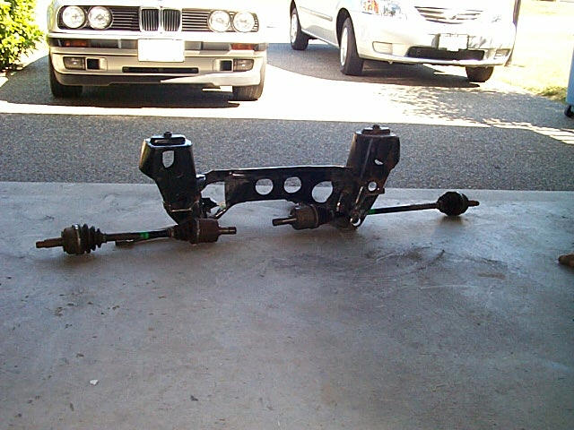
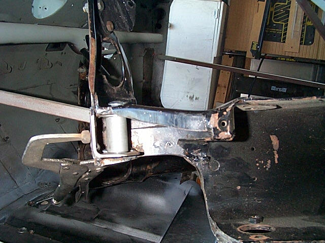
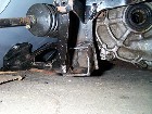
| 1. This shows both the drive shafts fitting through the frame. The
passenger side (RH) drive shaft hole was enlarged. The LH side part of
the sub frame was removed. |
 |
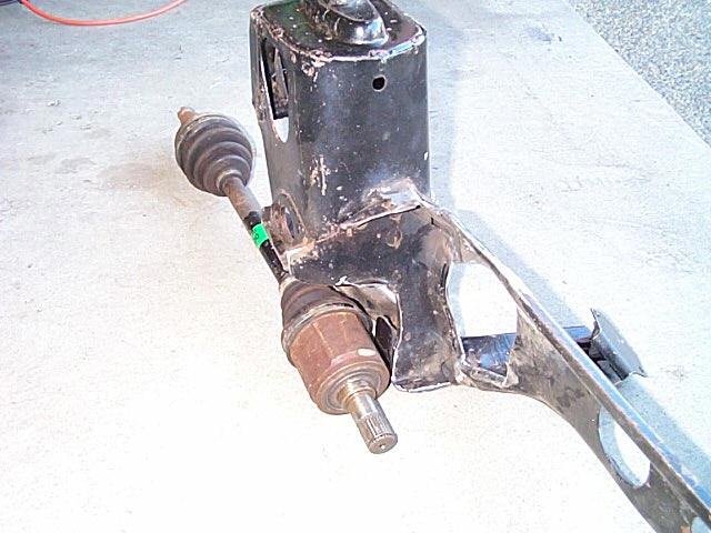
2. ...and the passenger side (RH) view shows the Honda shaft now fitting
through the hole. The hole was enlarged at both the front and the rear
of the opening. |
 |
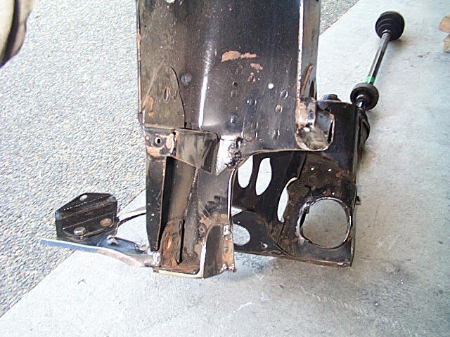
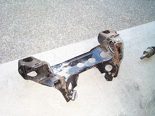
| 3. Another view of the RH side. the lower portion of the sub frame
was removed to allow clearance for the drive shaft. Then the problem of
mounting the lower arm had to be solved. |
 |
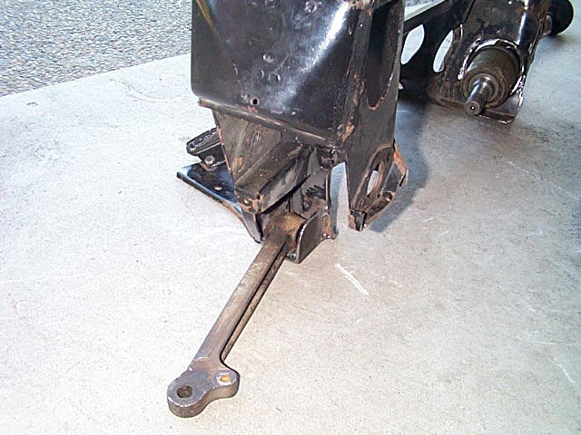
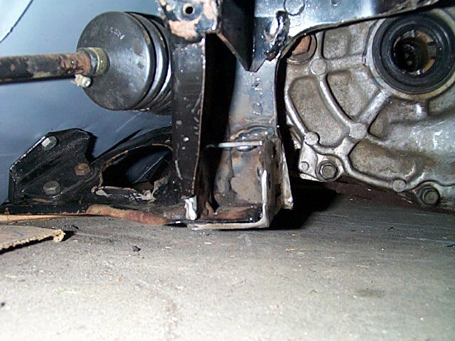
4. Here you can see the solution. I welded an angle iron piece from
under the sub frame up to provide a mounting point for a bolt that the
arm will pivot on, instead of using the odd shaped original bolt. |
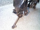 |
| 5. This gives a better view. The added piece is welded to the bottom,
rear and side of the sub frame and then rounded off. Bolt hole is not drilled
yet. |
 |
6. This shows what was cut away on the RH side, and another view of
the added section for the lower suspension arm. |
 |
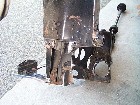
| 7. This is how the added piece was set-up. A spacer was mode to match
the distance required, centred using the original bolt hole and then clamped
for welding. |
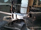 |
8. Before putting it back in the car for another check, I also added
another brace across the top, making more of a box assembly, as this will
add more strength. The sub frame was mounted in a drill press and the hole
for the suspension bolt was drilled. |
 |
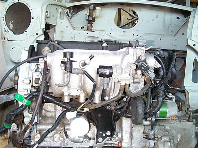
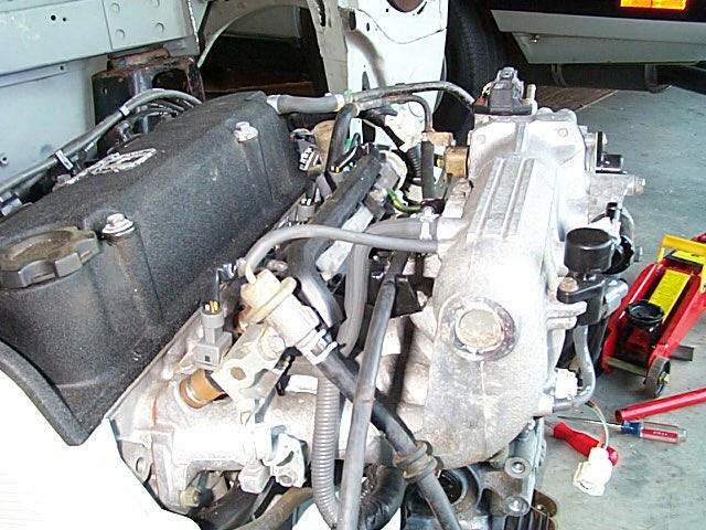
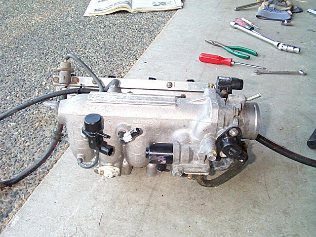
| 9. The spacing on the intake manifold is tackled next. You can see
that the manifold is very deep and will interfere with the brake master
cylinder and the crossbar on the firewall. |
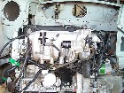 |
10. This shot shows how far back the manifold sits from the engine.
There is a support bar that goes from the back of the intake manifold back
down to the block to hold it up! |
 |
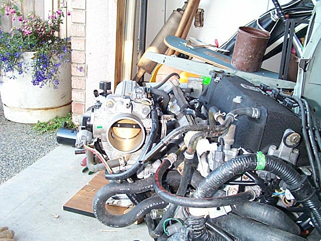
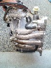
| 11. Another view of the intake manifold.. |
 |
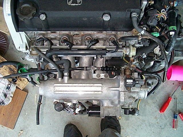
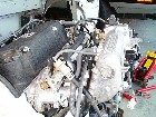
12. A top shot just before removing the intake manifold. Again you
can see how deep the manifold is. It is approx. 9.5 inches from the block
to the rear of the manifold. The space available is about 7.5 inches. |
 |
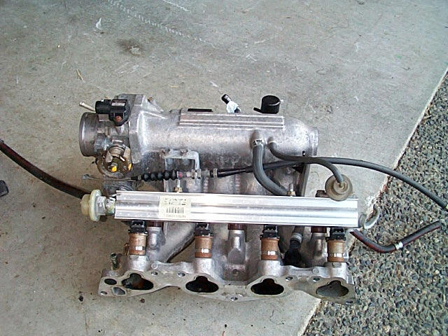
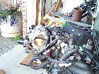
| 13. After removal. My plan is to have the manifold modified in a similar
manner to the purple car on the previous page. |
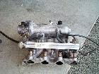 |
14. More shots.. |
 |
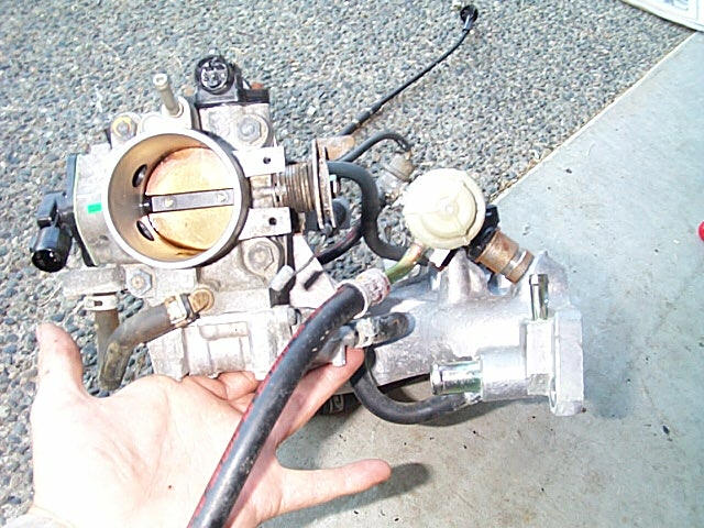
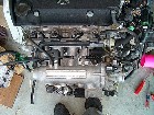
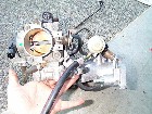
| 15. The throttle body assembly... |
 |
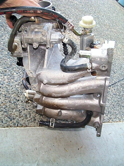
16. The long runners on the manifold..... |
|