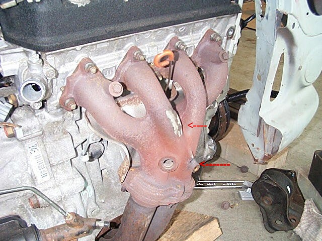
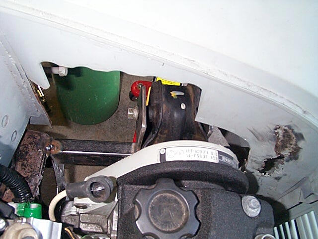
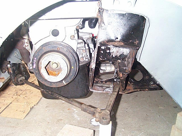
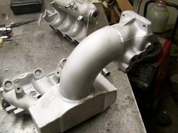
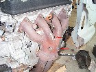
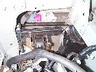
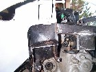
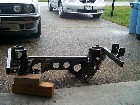
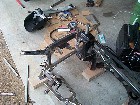
| 1. The red arrows show where the heat shield mounts are located. I
have already removed the top one and you can see the saw cuts as I start
to remove the lower one. |
 |
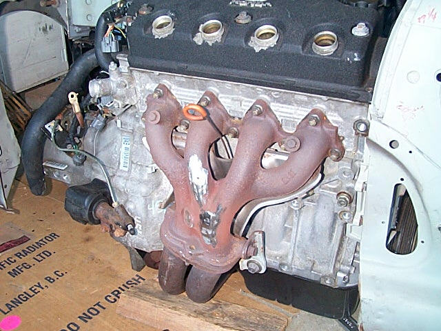
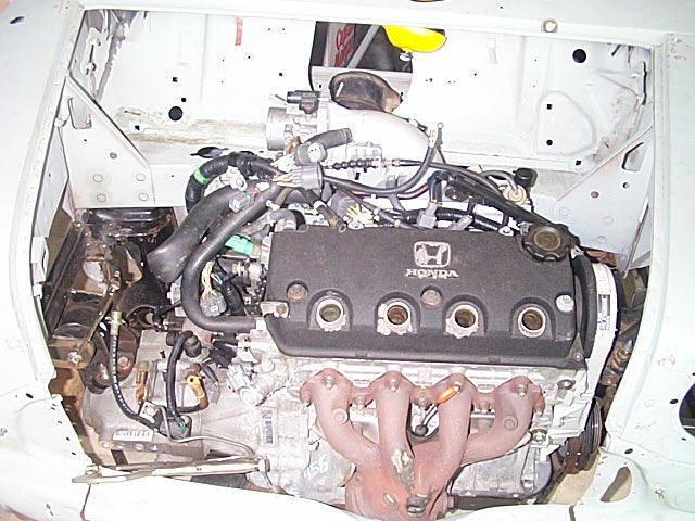
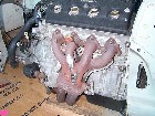
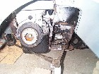
2. ...and the finished manifold, now giving me the extra clearance
required behind the grill. |
 |
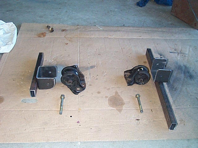
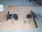
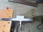
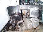
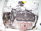
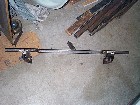
| 3. A view of the bits to be welded together for the support arms on
the sub frame. Arms, and brackets. The brackets are made from some 3" square
tubing with one side removed to make the U Also pictured are the engine
mounts. |
 |
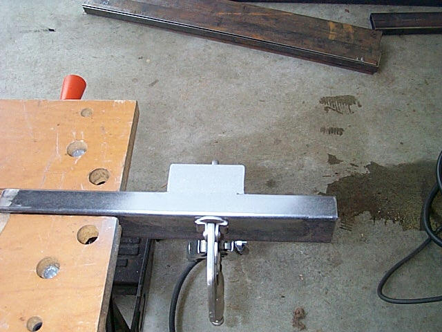
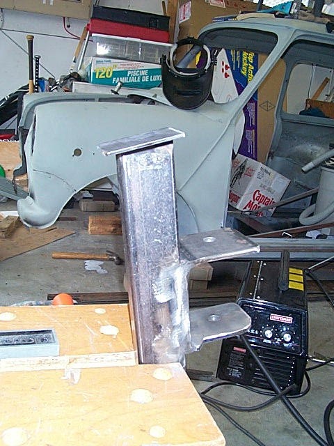
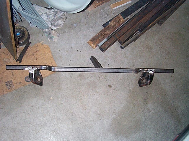
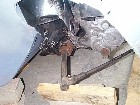
4. A view of the LH side support bar. I have welded on a short piece
of angle iron to help support the engine mount bracket. |
 |
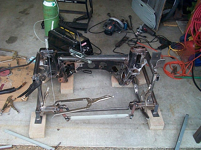
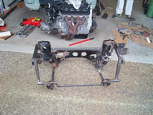
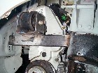
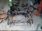
| 5. The RH side bars tacked in place on the car. The engine mount brackets
were welded to the support bars before, then the arm was held in place
and tack welded. |
 |
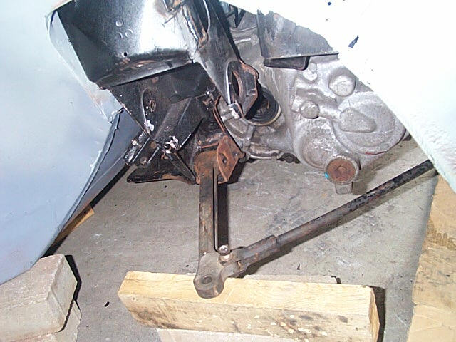
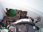
6. Here is a view of the LH side..again just tacked in place until
I pull out the sub frame for proper welding. |
 |
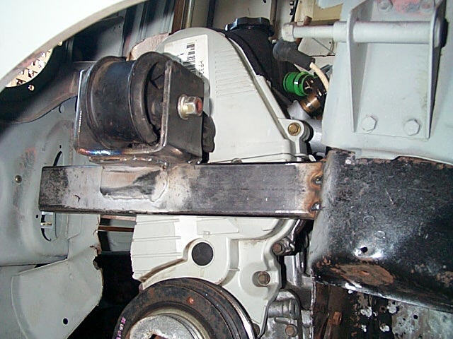
| 7. LH side viewed from the wheel well....you can see the extra angle
iron supporting the bracket. |
 |
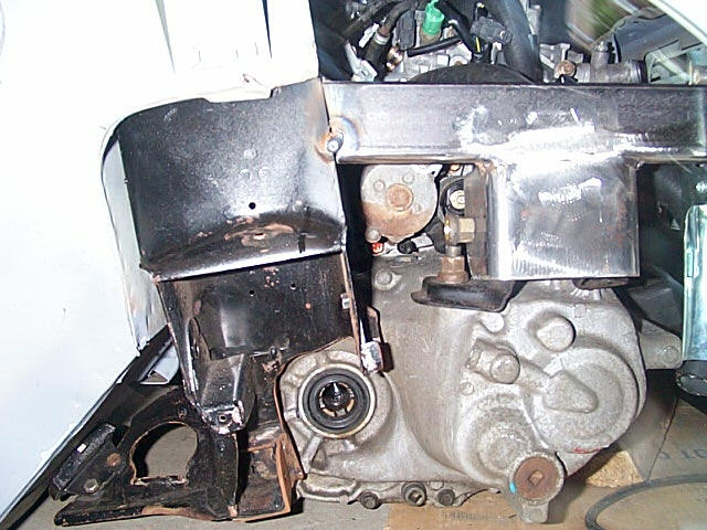
8. And the RH side from the wheel well...you can see the bracket welded
to the support bar. |
 |
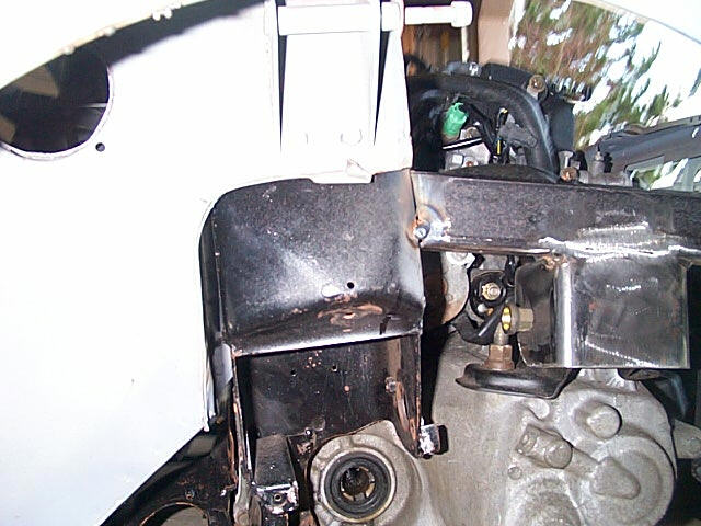
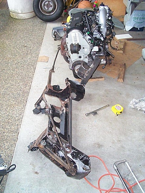
| 9. One last shot of the RH side... now onto the rest of the frame.... |
 |
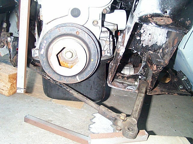
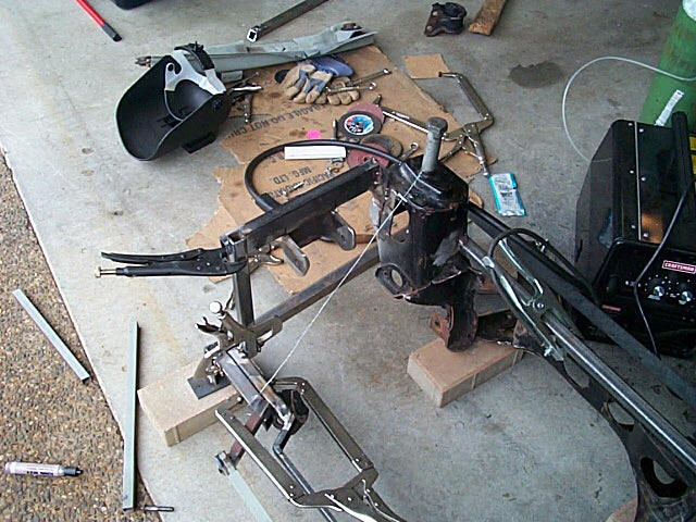
10. Well here I have run into a problem. The engine is sitting too
low so there is no clearance for the tie bars! I did not take into account
the sag for the engine mounts. |
 |
| 11. I've now pulled out the subframe and have added some 1/8 steel
plate to the back of the support arms so I can lift up the arms to raise
the engine higher. |
 |
12. I also added some 1/8 plate steel to the front of the tower to
add more area to weld the raised arms to.Here I've just cleaned up the
area to prep for welding. |
 |
| 13. You can see that the support arm is now higher than it used to
be. |
 |
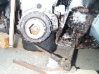
14. Now with the engine back in the car, I now have the clearance I
need and the drivehafts are still OK for alignment. |
 |
| 15. Still lots of hood clearance. You can also see the raised LH side
mount. |
 |
16. And lots of clearance on the LH side as well. |
|
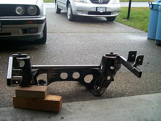
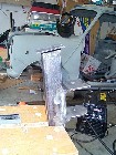
| 17. Here is the front bar where the front apron and the tie bars will
mount. Notice it comes out to go around the exhaust manifold. I used the
jig I built earlier to ensure the alignment between the body mount holes
and the tie bar brackets. The metal in the centre is just holding up the
bar for the picture. |
|
18. The tie bar brackets were cut off the old subframe and re-used.
The next step is to fabricate the rest of the frame sides and tie it all
together using the jig to keep the alignment correct. |
|
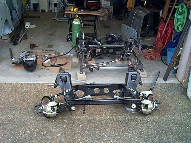
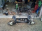
| 19. Here I have modified the jig to hold the subframe and it's getting
set up to weld the side bars in place, once alignment is confirmed. |
|
20. I am verfiying the measurements and alignment using a new subframe
and taking measurements from the tower bolts direclty to the body monting
bolts and diagonally as well. |
|
| 21. Here you can see the bar in place ready to be spot welded, and
the measuring wire in place. |
|
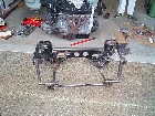
22. Here's the almost finished frame. Just some reinforcing bars, cleanup
the extra length on the ends of the bars, add the brakeline tabs, and the
final weld and painting to go. I'll post full meaurements after this is
done. |
|